Welcome. Scroll down to the topic you want:
1) Basics of Tomos Moped Electrical Systems Everything is Circuits, Shorts and Opens, Volts and Amps, Batteries and Generators, Magnetos, Magneto versus Battery, Testing without a Tester, Example 1: Prince of Darkness, Example 2: The Flasher, Make predictions, AC lights and DC lights, Example 3: The Double Crosser, Example 4: The Flickerer, Example 5: The No Charger
2) Tomos Voltage Regulators 1988 to 2013 Here are the 12 volt AC regulators, three types. One is also a rectifier.
3) Tomos CDI Ignitions 1994 to 2013 Ignition, How to Test a Coil, How to Check for Spark, Ground the Coil Wire to Stop the Spark, Tomos A35 and A55 CDI Ignitions, Ignition Timing, Ignition Symptoms
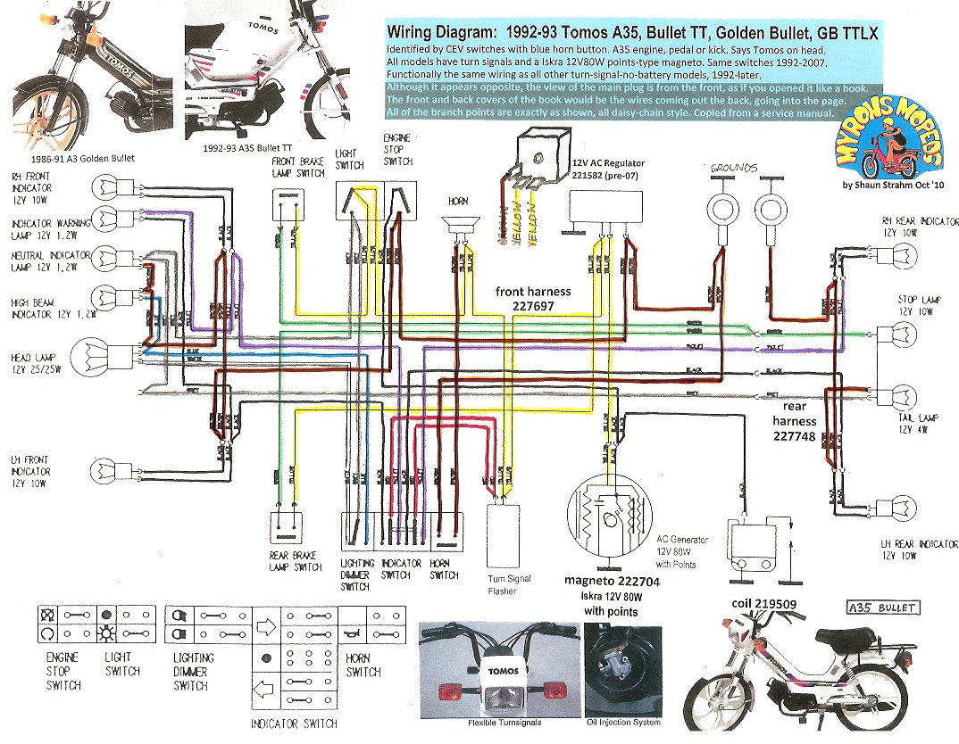
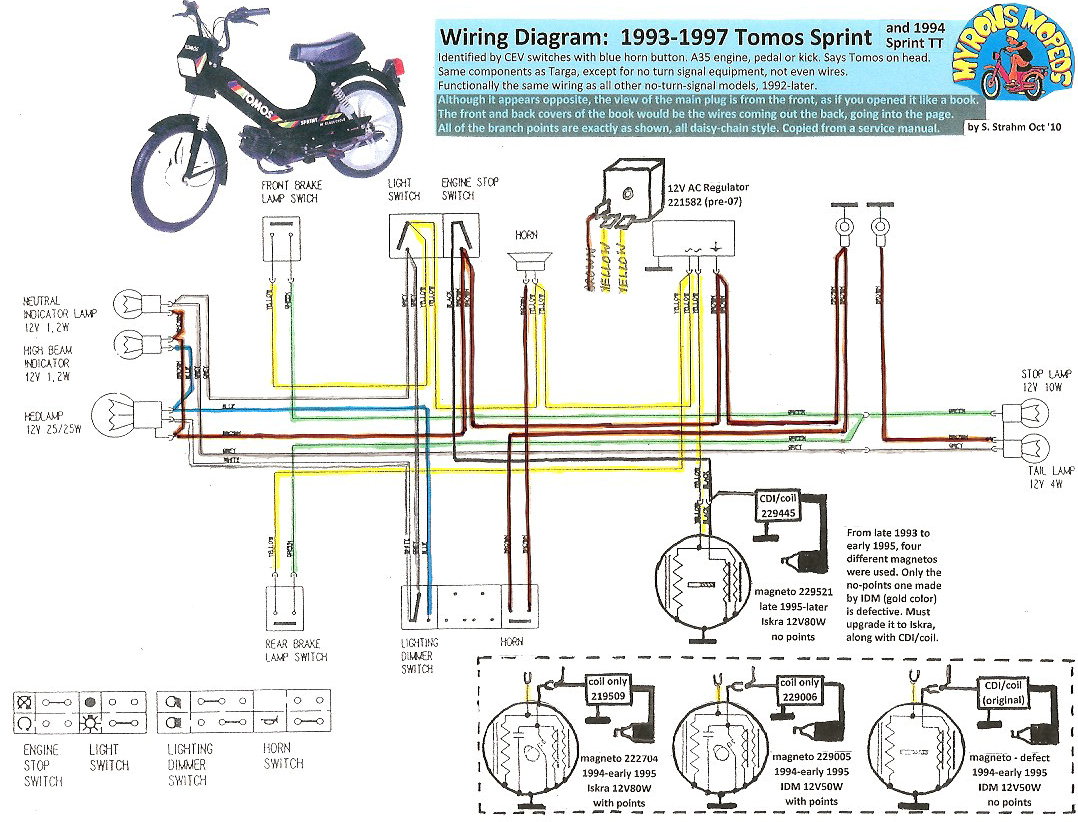
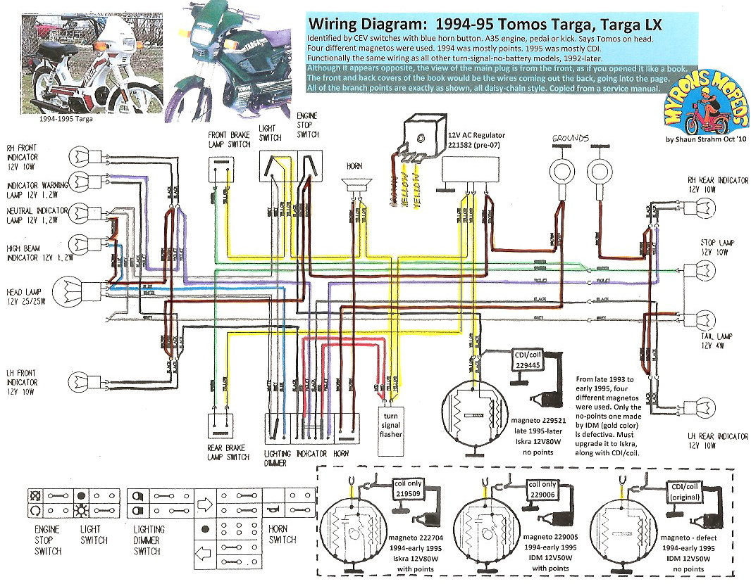
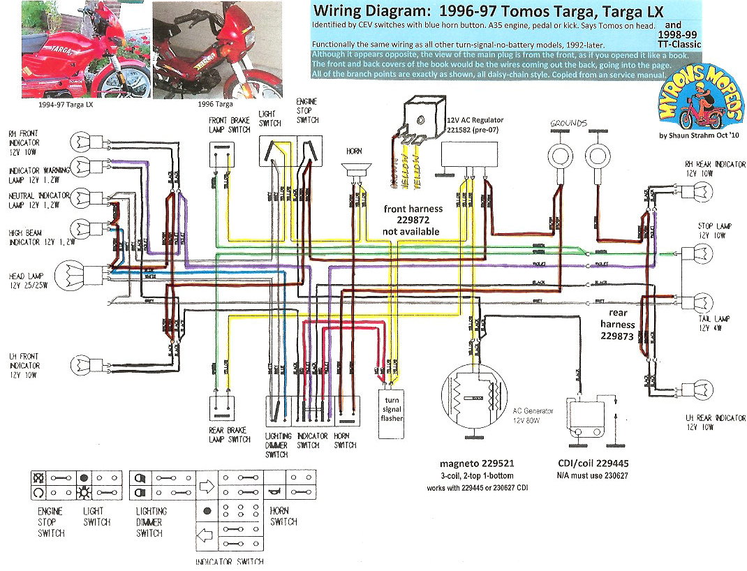
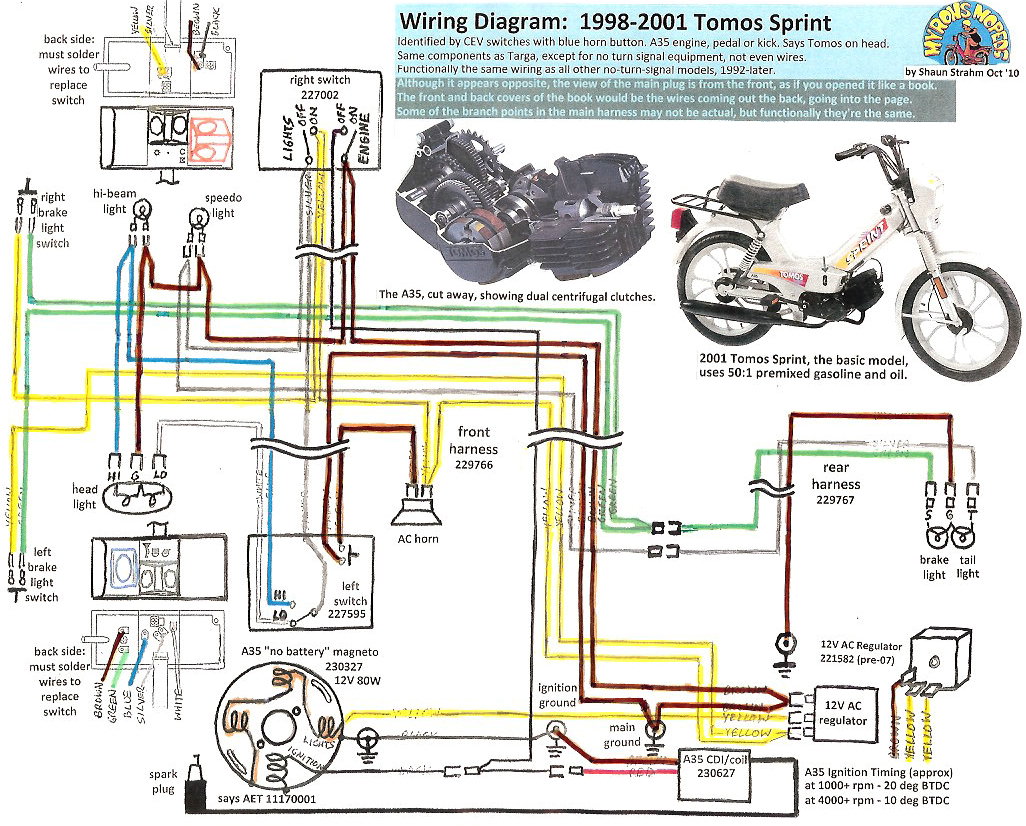
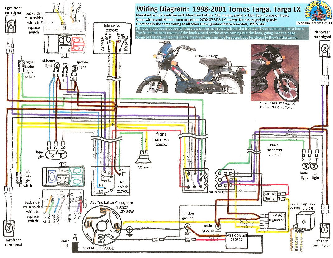
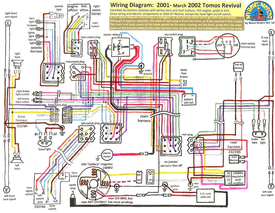
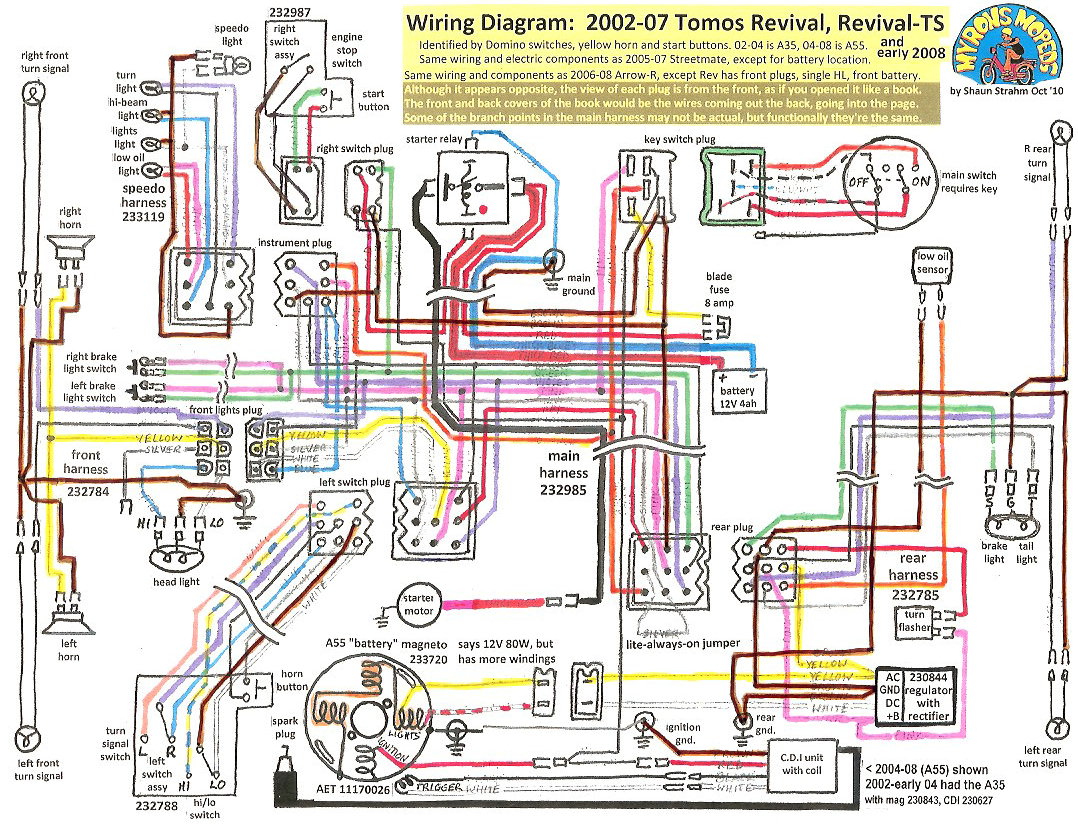
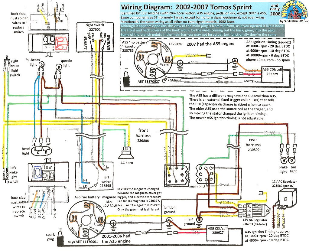
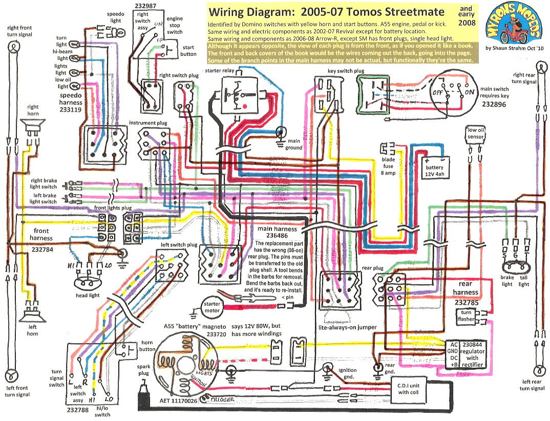
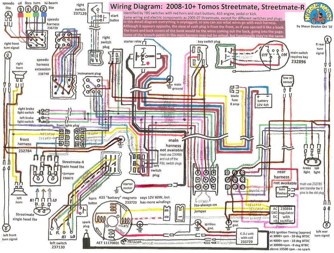
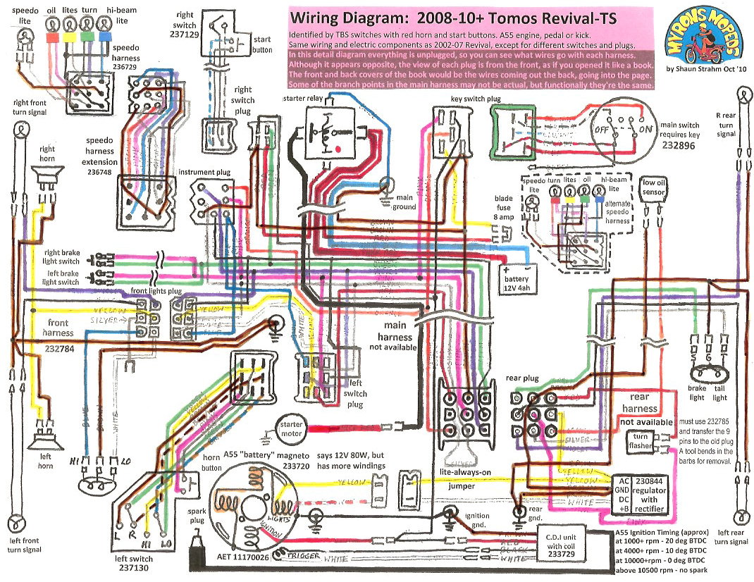
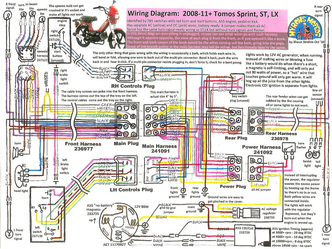
4) Tomos Wiring Diagrams 1992 to 2013 Here are over a dozen wiring diagrams, colorized and enhanced with notes, part numbers, and additional useful information.
Basics of Tomos Moped Electrical Systems
by Shaun Strahm, Myrons Mopeds, December 2010, updated Nov 2012
The following is a “crash course” on how to find and fix electrical problems on late model TOMOS mopeds.
Everything is circuits
Every electrical system is composed of current loops or circuits. The electricity flows out, goes through the device being powered, and then flows back. That is why all electrical cords have at least two wires. One wire is out and one is back. Coaxial cables look like one wire, but they’re actually one wire surrounding another. If you follow that pair of wires in an appliance cord all the way to the transformer on the power pole, you’ll see they’re joined in the windings of the transformer, forming a closed loop. In some electrical systems such as automobiles and mopeds, the metal frame is a “ground”. In this context a “ground” is a path for the electricity to flow through that is shared by many loops. If the cars in a big city were electricity, then each current loop would be one car, going to work in the morning and then coming back in the evening, making a loop. Then the freeway would be the ground, where the separate current loops all share the same roadway. When several devices are connected with each having its own current loop, they are said to be connected in “parallel”. Unplug one device and the others are unaffected. Everything in your house is wired in parallel, and has its own current loop. Similarly, on a moped, the head light, tail light, brake light, and horn are wired in parallel, and have their own separate loops or circuits. The tangled nest of cords behind your computer desk, as well as the wires in your moped, can, in principle, be laid out in nice straight parallel lines in order to visualize the “scheme”. This is called a “schematic” diagram. Being able to visualize or draw the schematic is required to understand any circuit.

Figure 1: Schematic diagrams of a moped and a house are the same. Every device is in a “parallel” loop or circuit.
When two devices are connected one after another, they are said to be “in series”. The only things on a moped or in your house that are in series with other things are the switches. From figure 2 below, you can see from the house wiring diagram that the TV switch turns on the TV and not the computer. You can see that the breaker turns off everything. From the moped wiring diagram you can see that the light switch turns off the lights but not the horn. This is basic.

Figure 2: The devices in a moped and a house are in parallel, while their on/off switches are in series.
You can usually tell how a moped or a house is wired from observing the behavior of all the switches and devices. Any switches must be in series with the devices they turn on and off. Each device and its (optional) switch must be in parallel so that they can be turned on and off independently of one another. This is predicting the wiring diagram from the observed behavior. Conversely, you can also predict the behavior from observing the wiring diagram.
Shorts and opens
Not every electrical problem is a “short”. The term “short” is unknowingly misused by the general public to mean two opposite things at once, a “short circuit” and an “open circuit”. It can mean a true short, where a wire (or anything that carries electricity) touches another, forming a shorter loop that redirects the electricity through the short loop and not through the original loop. Or the term “short” is misused to mean an open, where a wire (or anything that carries electricity) does not touch another, interrupting the loop and causing the electricity to not flow through the loop. Both a short and an open can cause electricity to not flow through a device, but for completely opposite reasons.

Figure 3: A “short” is a shortcut that steals most of the current from the device. An “open” interrupts the current.
Volts and amps
Electricity flowing through a wire is analogous to water flowing through a pipe. It is measured in two ways. The “voltage” (in volts), is like the water pressure (in pounds per square inch). The “amperage” (in amperes or “amps”) is like the water flow (in gallons per minute). When you’re taking a shower and someone turns on the garden hose, your water pressure drops. Less water pressure results in less water flow and your shower gets weaker. Likewise, when starting your car, all your lights get dim. This is because your 12 volt battery momentarily drops down to 6 or 8 volts when the starter motor is using up most of the available current.
Batteries and generators
There are two main sources of electricity. Batteries (and fuel cells) produce steady current, called “DC”, or direct current. Generators (and alternators, magnetos, and dynamos), make “AC”, or alternating current. The current made by a generator alternates direction back and forth, in sync with the rotation. The rotation is what causes the electric current to be AC. All power plant generators in the USA are set to rotate at a speed that always makes 60 cycles per second AC, or 3600 cycles per minute. On a moped, the generator rotates with the engine, which varies in speed from about 1000 cycles (revolutions) per minute “rpm” at idle to above 8000 cycles per minute going fast downhill. So the “frequency” (how fast it alternates) of the AC is variable in a moped, but not in a house. Many devices such as lights, behave the same no matter what the AC frequency is. In fact an incandescent light bulb works exactly the same on AC or DC current. In figure 4 below, graphs of voltage versus time show the main types of electricity. 60 wave crests happen in about one second, so the time scale is too short for the human eye to see. Only an oscilloscope can show the “wave form”.

Figure 4: AC is from generators. DC is from batteries. In between is rectified AC or “rippled” DC.
Magnetos
Mopeds and small motorcycles have magnetos. A “magneto” is a generator plus a no-battery ignition. A magneto ignition will operate with a dead battery. Automobiles and large motorcycles have battery ignitions. They require a battery, both to operate and to start up. Dirt bikes and power equipment without lights have magnetos with a single wire output. That is the ignition wire that goes from the source coil (and points and condenser) inside the engine to the transformer coil outside the engine. All street bikes with lights have two or more wires coming out of their magnetos. One is for ignition, and the other(s) is for lights. We now focus on the lighting wires, which are normally separate from the ignition. If you turn over a moped engine, that is, cause it to rotate, then some electricity will be generated and the lights should come on while it’s being rotated. Just because the lights work does not mean the ignition works. They are like two separate generators tuning on the same shaft. As the engine rotates faster, the lights get brighter, indicating more voltage is being produced. The magneto/generator will reach a speed where the voltage will level off. Above that speed the lights won’t get any brighter. So a magneto is self-limiting with regard to engine speed (and thus vehicle speed). The bad thing about a magneto is when you are stopped idling your lights are dim. With a battery, your lights are always almost the same brightness all the time. The good thing about a magneto is you don’t have a heavy expensive battery that goes bad if you leave it sit for over a few months.
Magneto versus battery
The most important difference between a battery and a magneto is a battery will deliver an almost unlimited amount of amps, if it is allowed to, while a magneto will limit the maximum amps by dropping in voltage. Because of this, a battery system needs fuses to protect its wires from melting from too many amps. A magneto does not ever have fuses, nor does it need them. This difference makes moped electrical troubleshooting different from automobile troubleshooting. A magneto almost never burns out or causes wires to melt. You can short a magneto’s lighting wire directly to ground, and it will only get warm. Short a battery’s positive terminal to the negative and the wire will suddenly glow red and splatter molten copper and sparks. That’s quite a difference. A battery is always “live” even when the engine is not running. A magneto, however, is only “live” when the engine is running. So when troubleshooting a magneto system, instead of starting and stopping the engine to perform voltage tests, it is more convenient to leave the engine off and perform continuity (ohms) tests on “non-live” wires. When the leads on an ohm meter touch each other, the resistance (ohms) is essentially zero. When the pair of test leads does not touch each other the resistance (ohms) is essentially infinite. Instead of watching the needle swing on a meter, a continuity tester that makes sound is better. With a tester that beeps when the leads touch, and with the leads connected to the wire being tested, you can then focus your eyes on the suspicious area and wiggle or move the wires around listening for the beep to change. When your suspicious wire touches the bad spot, the tester will beep. Or when your suspicious wire goes open, the beep will stop. This is the usual way of checking bulbs, besides looking visually for a broken filament. A good bulb will have continuity (very low ohms), while a bad bulb will have no continuity (very high ohms). You can often check a bulb without removing it from the socket, by connecting the test leads to the wires that lead to the bulb. If there are branch points along that wire that lead to other bulbs, then those other bulbs must be removed from their sockets in order to isolate the suspicious one.
Testing a without a tester
You don’t need a weatherman to know which way the wind blows. Likewise it is possible to perform useful tests with just swapping things around, unplugging things, or using paper clips or clip leads as temporary wires. When your toaster stops making toast, the first thing you do is go plug it into a wall socket that is known to work. Then if the toaster works there, you know the problem is in the wall socket. If it still does not work in the good wall socket, then you know something’s wrong with the toaster. Right there you just applied mathematical logic to perform troubleshooting. People who are good at math and logic puzzles also have an easier time solving electrical problems. The most important tool needed for electrical troubleshooting is the mushy grey stuff between your ears. Each test, when performed properly, establishes a new truth. The newly established truth forms the basis for a further test. Each successive test narrows down the possibilities, until finally there is only one possible explanation for the results of all the tests. There is almost always more than one way of troubleshooting. Instead of moving the suspicious toaster to a known good wall socket, an alternative way of troubleshooting it would be to take a known good lamp and plug it into the suspicious wall socket. If the known good lamp works there, then you know the wall socket is good and the toaster is bad. If the known good lamp does not work there, then you know the wall socket is bad but you still don’t know about the toaster. That is the kind of precise mathematical thinking required to solve electrical problems (puzzles to some).
Example 1: Prince of Darkness
Here is a real life moped troubleshooting example. Let’s say your 2003 Tomos Sprint head light does not work. You first learn about how it’s wired from the wiring diagram. That tells you there is a head light on/off switch on the right handlebar, and a high beam/low beam switch on the left handlebar. Right away you look to see if the switch is on. If it is, then you see if switching from high to low beam matters. On an already running bike, you would start the engine, flip the switches, and observe. If the head light worked on high beam but not low, that would mean the problem must be after the high/low switch, in the low beam (white) wire, low beam bulb socket prong, or most likely the low beam filament inside the bulb. If the head light did not work on either high or low, then nothing new is learned. Looking at the wiring diagram you can see that all of the lights work of one wire. So you would test to see if the tail light, brake light, speedometer light, and horn work. Again you would start the engine, press buttons, and observe. If none of the devices work, regardless of what position the switches are in, then it’s possible that all of the devices (head light bulb, speedometer light bulb, tail light bulb, brake light bulb, and horn) could be bad all at once. However, it’s far more likely to be a single fault in the yellow wire that supplies all the devices. There’s two ways the yellow wire can be bad. It can be touching ground anywhere along its length, from the speedometer bulb to the magneto, causing a short circuit, or it can be an open circuit somewhere before the first branching point, possibly in the magneto. Understanding that is the hardest part. The next test would be to unplug the yellow wire from the engine, start the engine, touch the yellow wire from the engine directly to ground and see if it sparks. If the generator is working, it will spark. Let’s say it does spark. Then you would look to see if it sparked when you plugged it back in, maybe using a paper clip to see sparks that might be hidden by the connector cover. If it does spark when it’s plugged in, yet none of the lights come on, it can only mean that the yellow supply wire is touching ground somewhere, allowing the current to return without going through the lights. Next step is to start eliminating the various possibilities. The AC voltage regulator is a good place to start. You would unplug it and then start the engine and see if the lights work. On a 1992-later Tomos moped you need a voltage regulator only when the engine is revved up to keep the bulbs from burning out from too much voltage (like 18 VAC max without regulator, 13 VAC max with). The lights will work fine without a regulator, but the engine must not be revved up too much. Let’s say that the test is performed, and the lights still don’t work, even with the regulator disconnected. Next possibility might be to look at the yellow wires going to each brake light switch, since they are easy to get to. Pull the rubber hoods off and let the wires hang loose, a yellow and a green on each side. Now if the brake light green wire was shorted to ground, and at the same time the yellow and green on either side were unplugged and touching each other , then the brake light would be always on, always stealing the juice from the other lights. You would start the engine with the brake light switch wires loose. Bingo! Suddenly the head light, tail light, speedometer light, and horn all work. So you would put the regulator back and then go look for the green wire touching ground somewhere. You know it must be true. You would look first under the back fender, where the tire sometimes rubs against the tail light and brake light wires. Eureka! The green wire is all shredded and touching the brown ground wire. You went from one end of the bike to the other, without any test equipment, just plugging and unplugging wires in a logical progression.
Example 2: The Flasher
In this example, a 2008 Tomos LX, turning on the right turn signal makes all the lights flash. You go to the wiring diagram and notice that all the devices run off the yellow AC power wire. You reason that if the purple wire, which is for right side turn signals, is shorted to ground somewhere, then that would explain the bad behavior. Whenever the right side turn signals would try to go on, the short would steal the current away and make all lights go off. The turn signals are plastic and almost never get shorted internally. It can happen from someone bending the prong that touches the bulb, so that it touches the bulb socket. But more likely, the purple wire is touching ground somewhere under the back fender. After looking under the rear fender and seeing no signs of wire damage from rubbing on the tire, you would start performing tests to isolate the problem. You would unplug both right turn signals. The problem would go away if it was in one of the turn signals. But it doesn’t. You study the wiring diagram and notice there are many ways you can unplug things on a 2008-later model. You might choose to unplug the main plug. From looking at the wiring diagram you would know that the front turn signals and indicator light would be eliminated, but the rear turn signals would still try to function. You perform the test, and lo and behold, the problem goes away. This means that the purple wire is touching ground somewhere from the main plug forward. You would then maybe look at the front harness where it goes up under the gas tank. A normal 2008-later Tomos Sprint, ST, or LX has the three electrical bundles and the two control cables (throttle and rear brake) distributed evenly on the right and left sides of the steering tube part of the frame. Some 2008-09 bikes came from the factory with all of the wires and cables on one side. This makes it very difficult to get the cable tray on and very likely to pinch or puncture the wires with one of the cable tray screws. You notice that your bike is like that, with the cables and wires all on one side. You loosen the cable tray screws, letting the wire bundles dangle. You plug back in the main plug and start the engine. The problem goes away. Then you notice the snake bite puncture wound the cable tray screw made in the front wiring harness. The permanent fix is to unplug the main plug, and the right switch plug, and relocate the front harness and right switch harness to the empty left side. So the right side should have the throttle cable, rear brake cable, and the left and switch harness. The left side has the hefty front harness and the slim right switch harness. With this proper routing the cables and wires almost never get damaged.
Make predictions
The troubleshooting process involves making predictions. Look at any of the Tomos moped wiring diagrams in the collection. Imagine cutting a wire or two, here or there, or touching one or more to ground. In each case a good technician should be able to predict the misbehavior of all the lights and devices for all possible cases, just by looking at the wiring diagram or visualizing it in their head. If you study each of the eighteen Tomos moped wiring diagrams in this collection and imagine what would happen when any given wire becomes open or shorted, then when you do see the real life misbehavior, you will often know right away what the possible causes are, since that scenario has already been rehearsed. For example, ask “what if the blue (high beam) wire touches ground”. Answer “all the AC lights would go off, but only when the high beam is turned on”.
AC lights and DC lights
The deluxe Tomos “battery” models, 2001 and later, including Revival and Streetmate, have both 12 volt AC and 12V DC electrical systems. Like the regular models (Sprint, ST, LX), the “battery” models use the 12V AC generator/magneto for the head light, speedometer light, and tail light. The other lights and devices, which are the brake light, turn signals, horn, oil light, and electric starter, are powered by a 12V DC battery.
Example 3: The Double Crosser
<Under construction>
Example 4: The Flickerer
 On 1991-2008 Tomos A35 and 2007-2008 A55 models, excluding Revival and off road, the CEV switches are integrated into the lever and throttle housings, and cannot be unplugged from the wiring harness. To replace these switches, each wire must be carefully un-soldered and re-soldered. A micro-tip low wattage soldering iron is needed to reach in, and to not melt the black plastic housing. Sometimes when trying to not overheat the switch plastic, the solder joint is made “cold”. This is where the solder is “balled up” rather than “blended in”, where it is stuck only by the flux and not the solder. Here, the blue hi-beam wire is a “cold” solder joint. When you wiggle the wire it causes the high beam to flicker. The remedy is to re-solder it.
Example 5: The No Charger

This 2009 Tomos stator, back side, had this wire, green arrow, smashed flat against the aluminum wall of the stator plate. It was not touching all the time. The coils do not look overheated.
This machine was a 2009 Tomos Streetmate-R, a “battery model”. It’s battery would not stay charged. The battery voltage was staying the same, whether the engine was running fast, or not at all. It should go up, from about 12 to 13 volts, when it’s charging.
You can tell from 50 yards away, blindfolded, whether or not a Tomos Revival, Streetmate, Arrow-R charging system is working, by the sound of the horn. When the battery is not being charged, like when the engine is not running, the horn sounds completely smooth. The battery voltage is a steady straight line on an oscilloscope. When the engine is running the the smooth sound becomes more rough. The battery voltage is a straight line with little repeating bumps on an oscilloscope. When you hear the rough sound in the horn, you know that the charging system is working.
The white spot is a reflection from the shiny flat surface of the black insulation, worn from vibration and contact with the stator plate. The fix was to cut away a fingernail size part of the plate.
Tomos Voltage Regulators
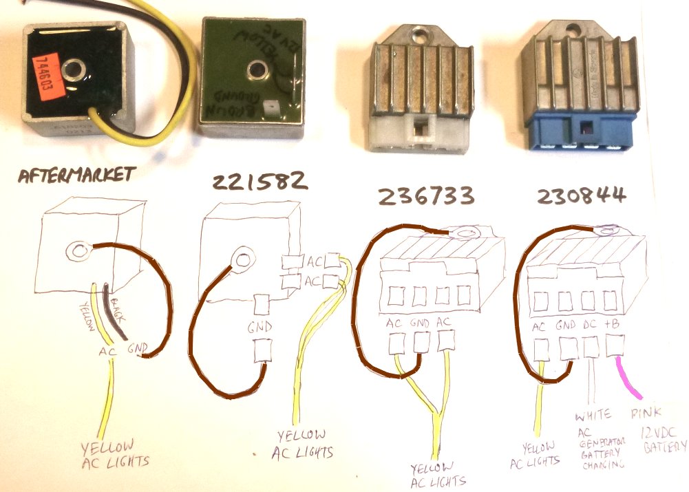
Tomos regulators. Some blade connectors are duplicates (connected together inside) or unused (not connected inside).
All of the above 12-Volt Alternating Current regulators can interchange. They all regulate the voltage on the yellow wire, by dumping any excess voltage into the brown wire, that goes to the frame. They keep the AC voltage below about 13 volts. This allows the use of a stronger generator, for brighter lights when stopped and the engine is idling. The stronger generator would otherwise be too strong when the engine was running fast, and would make a voltage over 13 volts, maybe 14 or 16. That would make the lights super bright, but they would soon burn out. The regulator prevents bulb burnout from too much voltage. The bulbs can also burn out from too much vibration. The regulator would not help that.