Table of Contents
Ignition …………………………………………………… 1
How to test a coil……………………………………. 1
How to check for spark…………………………… 1
Ground the coil wire to stop the spark….. 2
Tomos A35 and A55 CDI ignitions…….…….. 2
Ignition timing………………………………………… 2
Ignition symptoms…………………………………. 3
Ignition
The ignition is like the electric pulses of a heart beat. The voltage pulses are in sync with the rotating crankshaft. When the crankshaft rotates faster (or slower), the spikes are closer together (or farther apart) in time. See figure 5.

Figure 5: Ignition is neither AC nor DC, but instead a train of narrow pulses, each happening at a precise time.
What makes the gasoline ignite is the spark plug sparking, in the right way, at the right time. What makes the spark jump the gap of the spark plug is a sudden very steep rise in voltage, to over 10,000 volts in under a few thousandths of a second. What makes that high voltage spike is a transformer, usually called “the ignition coil”. A transformer is like a car jack. It steps up (or steps down) voltage while stepping down (or stepping up) current. A sudden change in current in the (thicker but fewer) primary windings induces a sudden large change in voltage in the (thinner but many more) secondary windings. Supplying the transformer with a sudden change in current is either a CDI unit (Capacitor Discharge Ignition), on 1994 and later, or a mechanical points and condenser, on 1993 and earlier models. On late model Tomos mopeds with CDI ignition, the electronics are molded into the coil (unlike most Asian types). The “control unit” or “CDI unit” is a small 1.5 inch square circuit board, hidden inside the black plastic of the coil. Early models before 1994 had plain coils, without any electronics.
How to test a coil
Any ignition coil (coil only, not coil-with-CDI like Tomos uses) will produce a spark on a spark plug, at the instant the input wire is touched to a 12 volt battery (+), with the battery (-), coil, and plug all grounded (with clip leads). If you touch it slowly to the battery post, it will produce a weak spark. If you swipe the coil wire fast and hard against the battery post, it will produce a strong spark. This demonstrates that it’s the shorter “rise time”, much faster than the blink of an eye, that makes a better spark. Only perform the above spark test on plain coils. CDI/coils might get damaged from the high current possible. Never connect a 12V battery to a coil for longer than one second. It turns out that moped coils are never bad. Only occasionally the CDI/coils go bad. “Bad” means it produces no spark at all, or it produces weak or intermittent spark. Intermittent spark is like turning a light switch off and on, often in an unpredictable way. The only way to test a CDI/Coil is to put it on a known good running bike and test ride it, listening and feeling for any stumbling or misfiring. If no test bike is available, then the only way to test the CDI/Coil is to replace it with a known good one, and hope that fixes the problem. If it’s not the CDI/Coil, and not the bike’s wiring, then it must be the magneto. The CDI magneto costs way more than the CDI/Coil, and is more difficult to change, and so it’s last.
How to check for spark
CDI solid state ignitions have shorter rise and fall times than mechanical point ignitions. That makes them start with a weaker kick, or even with your hand. CDI ignitions have a faint spark that is sometimes invisible in bright sun. Always check for spark in the shade. “Checking for spark” means removing the spark plug, connecting the plug wire to it, laying it on the engine so that it’s metal shell is touching ground (the head fins), and then turning the engine over (by pedaling backward or kick starting) while watching the gap between the electrodes of the spark plug. Spark color indicates temperature. Blue spark is hotter than pink or yellow. Faint blue spark is good. Bright white spark is bad, usually because of a semi-conductor-coated “fouled” spark plug. The white porcelain insulator must not be coated with black or shiny carbon. If it is not dull white, tan, or brown, then use a new spark plug to check for spark. A fouled plug will spark badly or not at all, even when the ignition is working fine. You can also hear the snap sound of the spark. Loud is good.
Grounding the coil wire stops the engine
In both CDI and points type magneto ignitions, the “heart beat” is intentionally stopped when you turn the engine stop switch off. When the “kill” switch is “on” the ignition wire is not grounded. When the kill switch (engine stop) is “off” the ignition wire is grounded. This is the opposite of a (battery ignition) car. So to hot wire a magneto ignition bike you only need to disconnect or cut the kill switch wire so that it cannot be grounded. When troubleshooting a late model Tomos that has bad or no spark, the way to eliminate all the wires in the bike is to plug the black (or red) magneto ignition wire (which has a female blade connector) into the male blade of the coil (or it’s black or red wire with male blade). This isolates the circuit to just the engine and coil. Just remember you can’t turn the engine off.
Tomos A35 and A55 CDI ignitions
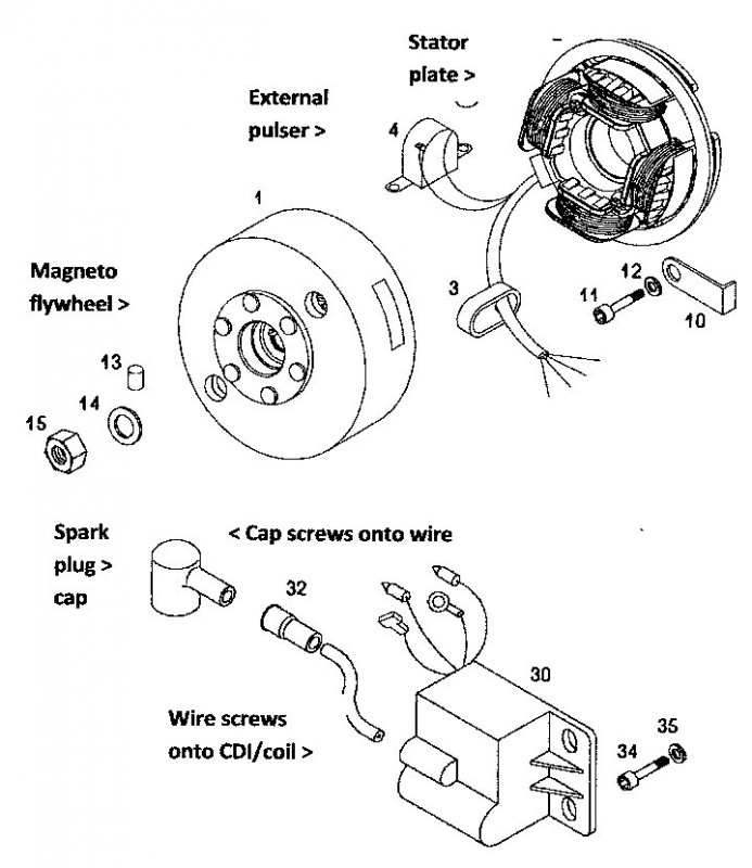
There are two types of Tomos CDI magneto ignitions, the A35 type (1994-2006) and the A55 type (2001-later). They consist of two or more coils mounted on a stationary plate, surrounded by a rotating flywheel with four strong magnets molded into it. The A35 ignition has no pulser coil to tell it when to spark. It triggers when the source coil voltage reaches a pre-set level. So changing the location of the source coil (by rotating the stator plate) changes the ignition timing. Tomos provides adjustment slots in the stator plate, and timing marks (thin angled black lines) on the crankcase (minimum and maximum ignition timing), at about the 10 o’clock pposition. An ignition timing strobe light is the only way to check the ignition timing. The strobe light illuminates the fast moving flywheel mark only for an instant. So it appears, magically, to be not moving. The fire mark on the flywheel should lie between the black lines on the case. It should not jump around. The light should not flicker. Once the stator is set in the desired position and the screws are tightened, the timing is set forever, and never needs adjusting (that is assuming the flywheel locating key is in its proper place and the flywheel nut is fully tight). Unlike the A35, the A55 ignition does have a pulser coil that signals the control unit when it’s time to spark. It’s an external pulser (or exciter or trigger) coil that senses a raised strip on the outer edge of the steel flywheel/rotor. So changing the stator position does not change the ignition timing. The A55 external pulser is fixed and mounted in a way that prevents it from being adjusted.
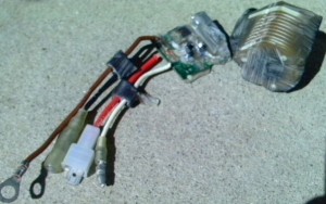 Left, grinding away the plastic reveals the CDI circuit board and the coil of 233729.
Figure 6a: A55 “no battery” ignition exploded view Figure 6b: Same ignition shown in a semi-schematic diagram
There are about ten different Tomos magnetos for the A35 and A55 engine series. They are all covered in detail in the wiring diagrams collection that this written text supplements. There are also a few more for the earlier A3 models. Before 1986, Tomos A3 mopeds had an external ignition ground that powered the brake light. On those early models if you unplugged the brake light, and then squeezed either brake, the engine would lose spark and cut out. Those early A3’s, with 3-wire magnetos, yellow, black, and blue, often need the blue magneto wire to be grounded in order to have spark. After ‘86, all Tomos magnetos are 2-wire magnetos, yellow and black, with no external ground, one less worry.
Ignition timing
The spark occurs a little before the piston reaches top. That explains ignition timing in one simple sentence. Spark happens before top because the gasoline and air take a tiny bit of time to burn. If the spark happened right at the top of the piston stroke (“top dead center” or TDC), the engine would run, but be weak. If the spark happened twice as early as it should, the engine would run, but be weak and run hot. There’s a preferred range where the “porridge is just right”. Expressed in terms of crankshaft angle, the preferred ignition timing is between 10 and 20 degrees before top. Imagine the flywheel is a pie. Cut the pie in six pieces and you have 60 degree slices. Cut one of those pie slices in three thin slices. That would be a 20 degree angle. That thin slice is a little less than an inch wide on the edge of the flywheel. The time taken for the wheel to move that much is about the time taken for the gas to ignite. At 6000 rpm the piston rises every 0.01 second. Expressed in actual seconds, at 6000 rpm, the spark occurs .01*20/360 = 0.00055 seconds before the piston reaches top. That’s half of a thousandth of a second. You don’t need to know that to fix mopeds, but it makes the lesson interesting and amazing. The faster the engine turns, the less time the fuel has to burn. Because of this, most gasoline engines have variable ignition timing, rather than fixed timing. Four stroke engines like the timing to be about 10 degrees at idle, advancing to about 35-40 degrees at high rpms. They have vacuum advancers, centrifugal advancers, and electronic control units (ECU), to vary the ignition timing automatically. Two stroke engines like the timing to be about 20 degrees at idle, retarding to 10 degrees at high rpms. The explanation is better atomization at higher engine speeds makes smaller fuel droplets which take less time to burn. Before 1994, Tomos A35 mopeds had points, with fixed ignition timing, 20 degrees BTDC. From 1996 on, they had Iskra CDI, with variable ignition timing, 20 deg at idle changing to 10 degrees above about 6000 rpm. The only way to see the timing is with a strobe light made for automobile ignition timing checking. To actually measure the degrees, cars use a thing called a “degree wheel” that attaches to the crankshaft. Any piece of paper with accurate degree lines can be attached to the flywheel, but putting it in the exact correct position is difficult. There’s a clever and simple procedure for finding top. A tool called a piston stop is screwed into the spark plug hole. The crankshaft is rotated by hand until the piston is parked up against the stop. A line is made on the flywheel, adjacent to any chosen case mark. Then the crankshaft is turned by hand the other way until the piston is again parked up against the piston stop. A second line is made on the flywheel adjacent to the case mark. Then a tape measure is laid around part of the flywheel to find the midpoint between the two marks. That is “top dead center”. Fortunately the Tomos flywheels already have inscribed timing marks, one for top, one for fire, spaced 20 degrees apart. The F mark should be between the crankcase marks, when viewed with the strobe. The newer A55 engine mopeds have the same ignition timing but it is not adjustable like the A35 is. That’s Tomos saying don’t mess with a good thing.
Normally, ignition timing is never an issue with CDI ignition 1994-later Tomos mopeds. That is because those magnetos are maintenance free. It is, however, often an issue on the earlier points-ignition models. This is because the ignition timing gets retarded as the points rubbing block wears down. So points need adjustment (spread apart to have more “gap”), and lubing with high melting point grease, every few thousand miles. Besides that, they can be adjusted wrong. The points are designed to open at the right moment in a running engine, when at fully open in a stationary engine they have a gap of .014 to .017 inch (.35 to .45mm). In a magneto with points ignition, the spark happens when the points open, not close. That is essential to know. You can spot check the ignition timing of a points model with nothing but a pen and a flashlight. Find TDC with the pen in the spark plug hole. Rotate backward 20 degrees and see if the points are just starting to open there. In both points-ignition and CDI ignition, the flywheel can be installed in the wrong position on the crankshaft by leaving out the little locating pin. That’s not a normal thing. Neither is running with a loose flywheel nut until the pin shears off and ruins the crankshaft and flywheel. Ouch. It’s also not normal to have some other flywheel, like from a Puch, Sachs, or aftermarket one that has no timing marks or is sparking at the wrong time. A bunch of different moped flywheels will fit the Tomos crankshaft, but they might have the wrong ignition timing because of a different point cam angle. Some stator plates can be installed upside down, making the timing 180 degrees off. Only in these not-normal circumstances you might need to mark the flywheel and check the ignition timing.
Tomos A55 Ignition
Here are some pictures of a 2011 Tomos ST magneto.
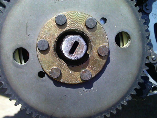
Above, after 2009, the flywheel says “Kinetic 12V60W”. Rotation is counter clockwise. Since 2010, all models, kick start and electric start, have the outer gear for electric start. That gear blocks the view of the “pulser” or “timing coil”, black at lower right.
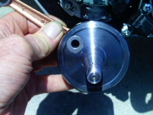
Above, a Tomos A35/A55 crankshaft held at the same angle as one in the engine. Roughly speaking, the cylinder is tipped forward to the 10 o’clock position. Here the connecting rod is pointing straight up the cylinder, which is “top dead center (TDC)” or the top of the stroke. When the crankshaft is in the TDC position the crank pin is at 10 o’clock. Then see the little hole in the tapered shaft pointing at you? It is where the flywheel “key” or “roller” or “pin” goes. The flywheel key is at 11 o’clock or 11:30. Right above the crankshaft is the black-wrapped ignition source coil, that’s fixed to the stator. In the upper right corner is the Kinetic pulser, black plastic that’s kind of rough. It is fixed to the crankcase at the 4:30 clock position. This angle, plus the crankshaft key hole angle, plus the angle of the “timing strip” on the flywheel, relative to the key groove (not shown), plus any retard or advance added on by the electronic module or “CDI unit”, is what determines the ignition timing.
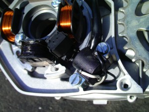
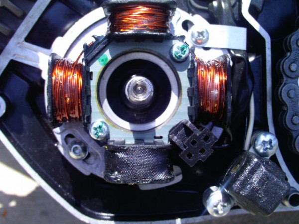
Above, two views of the A55 “stator” or stationary part of the magneto. Three clear-coated copper lighting coils are seen at 9 o’clock, 12 o’clock, and 3 o’clock. The 90 degree spacing matches the four magnets inside the flywheel, not shown. The 3 lighting coils are connected in series, grounded internally, and emerge as the yellow lighting wire. Branching off one of the lighting coils is an additional white/red battery charging wire, not shown. At 6’oclock is the black ignition source coil, not connected to the others, emerging as the black ignition wire. At 4:30 is a black plastic junction box. Also at 4:30, but further out, outside of the flywheel, is a rounded black plastic one inch cube called the “pulser” or “trigger coil”. It tells the CDI control unit when to fire the spark plug, at a precise crankshaft angle. Not shown is the flywheel or external “rotor”, with a raised strip of metal that triggers the spark timing. Notice how the white pulser wire is on the bottom and the black pulser wire is on top. If they are reversed, the ignition timing will be way (like 40 degrees) too early, and the engine will run poorly. The left photo is a 2007 stator, by AET, made in Slovenia. The right photo is a 2011 stator, by Kinetic, made in India. They are both good and interchangeable.
Ignition symptoms
<Under construction>